THE ELECTRONICS
CLICK PICTURES FOR LARGER IMAGE

|
|
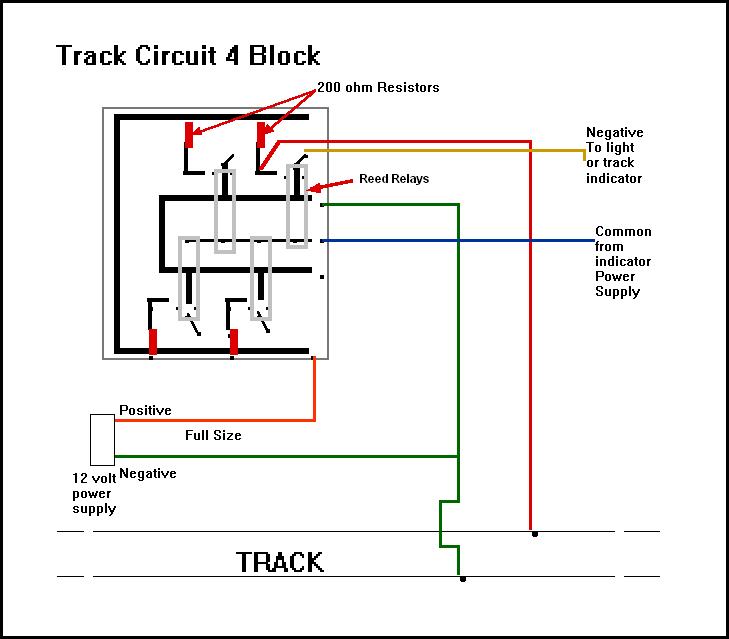
THE TRACK CIRCUIT
This is the track Circuit used for operating the signals on The Redlake Junction Railroad. The main problem with Signals in our hobby is snow and rain on the track. Snow and rain conduct electricity and will show the false presents of a train in a block. I have tested this in both snow and rain and it works well. The circuit works with the track completely submerged in water !!! The type of ballast that you use and the moisture content of your soil also effect the operation of the circuit. I have used it with 1/4 minus crushed river rock ballast and volcanic cinders with good results.This is not a fail safe system. What I mean by this is that it does not protect you from component failure or power loss. Full size railroad signaling that costs thousands of dollars protects against a false clear (Green) indication with many system back up circuits and is fail safe. I will not be responsible for damages caused by this circuit. You use it at your own risk.
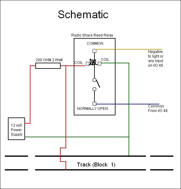
With that said all you need is two components for the circuit: Radio Shack Reed Relay Catalog #: 275-233200 OHM 2 Watt Resistor (I use the NTE Brand Just make sure it is 2 Watt) DO NOT SUBSITUTE PARTS. PLEASE NOTE THAT THIS IS A 2 WATT RESISTOR You can build these on PC Boards using the Radio Shack PC Board Kit Catalog #: 276-1576 and make several circuits at once. I build 6 circuits on each board because a sideing will have 6 blocks. 1 Block for the sideing 1 Block for the Mainline 1 Block for the East Approach 1 Block for the West Approach 2 “OS” Blocks to protect each turnout
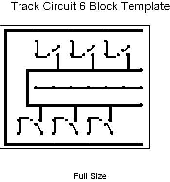
Print the circuit board template out and tape it to the PC Board. Full size when printed should be 4 ¼ inches by 3 ½ inches. Drill the holes then connect the holes like the lines on the template using the ink pen in the Kit. I use a smaller drill bit then the one in the Kit. Use a drill bit that will fit the biggest wire you solder to the PC board snugly. Follow the instructions in the PC board kit to etch the board then solder the components in. The Reed Relay is always closed until a train enters the block then the Reed Relay will open. |
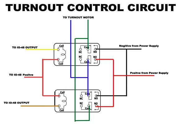
THE TURNOUT CONTROL CIRCUIT
The Turnout Control circuit uses two Radio Shack DPDT Relays Part number 275-249. A pair of outputs on the IO-48 will operate one or the other relay to get the DC motor on the turnout to throw either NORMAL or REVERSE. The Oaktree software will send a 300 millisecond pulse that will close the relay and send 12 volts to the motor. I use the Ryobi 3.6 volt cordless screwdriver for a turnout motor. The batteries are removed and they run just fine on the 300 millisecond pulse of 12 volts. If the motor has a short wire run to the power supply a 10 or 20 ohm wire wound resister can be added in series with the screwdriver. The screwdriver needs to have the ball bearings removed that are up in the nose so it will freely move to have the option to line the turnout manually.
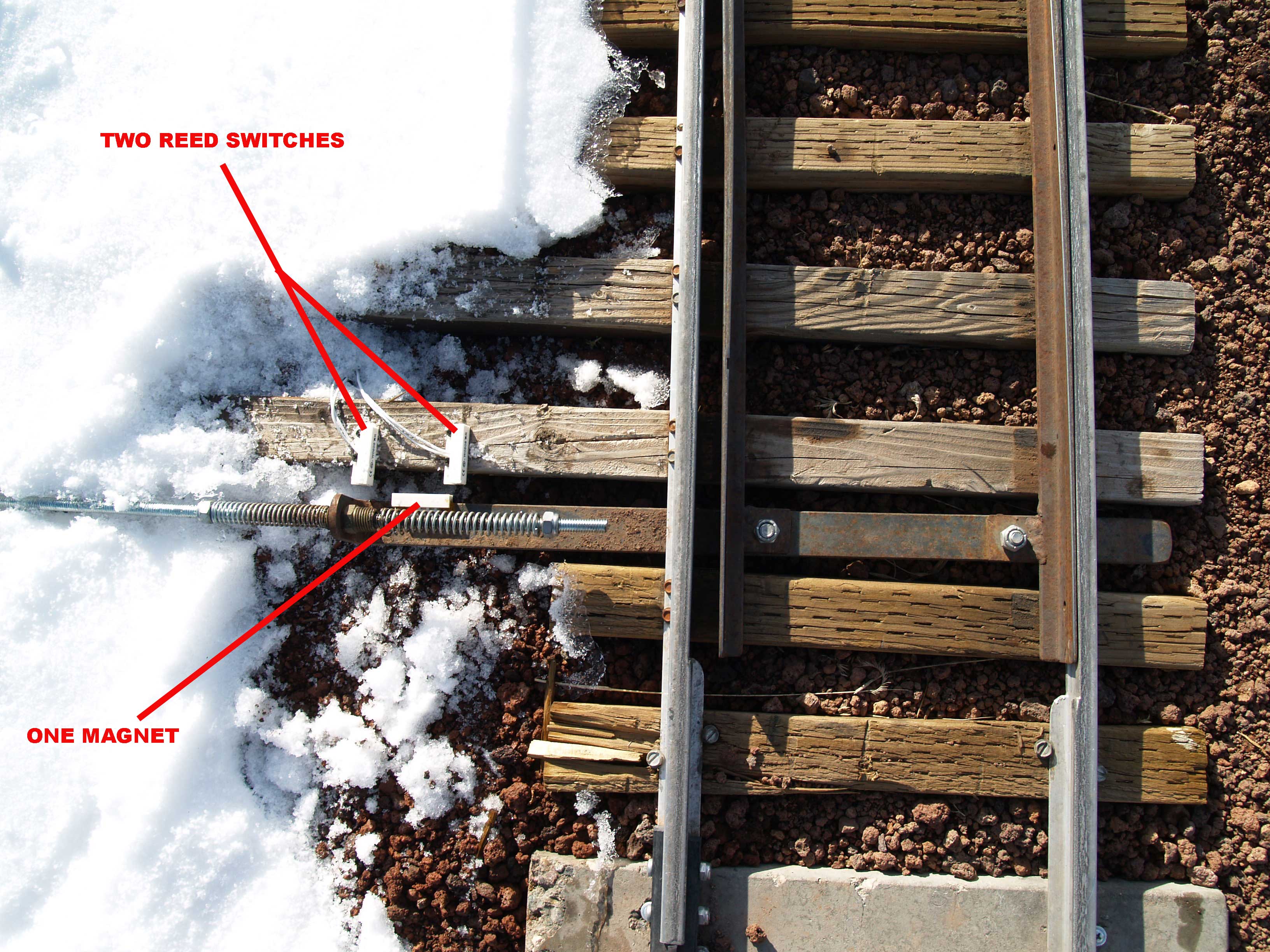
Each turnout is a little different with the milliseconds that it takes to throw it. I start with 200 milliseconds and work up until it throws good. If you get up to 600 milliseconds and it is still not working check the turnout linkage for binding. The only other electrical to the Turnout is to add the reed switches to the turnout points. You want the reed switch to just close as the switch points do. The photo below shows how I mount them on the turnout.
The output of the reed switches connect to 2 of the inputs on the IO-48 Card. |
COMPUTER INTERFACE
I use the Oaktree Systems Model RR interface system by RCS to control my signals and Oaktrees software. Pictured above is their IO-48 card. An IO-48 card has a total of 16 inputs for things like the track circuit card to give it block information and turnout control feedback from the magnetic reed switches to show the position of the turnout points. I also use the inputs to connect push buttons so that the turnouts can be thrown by an engineer on the fly to select his route without stopping. The
IO-48 card has 32 outputs for signals and switch motors. Four 3 aspect signals (Red, Green and Yellow) 2 double headed signals (Red, Green and Yellow on top head with red and yellow on bottom) 2 outputs for each of the 2 motors on the turnouts 6 inputs for the 6 blocks 4 inputs for the position of turnout points on the 2 turnouts 6 inputs are unused
I
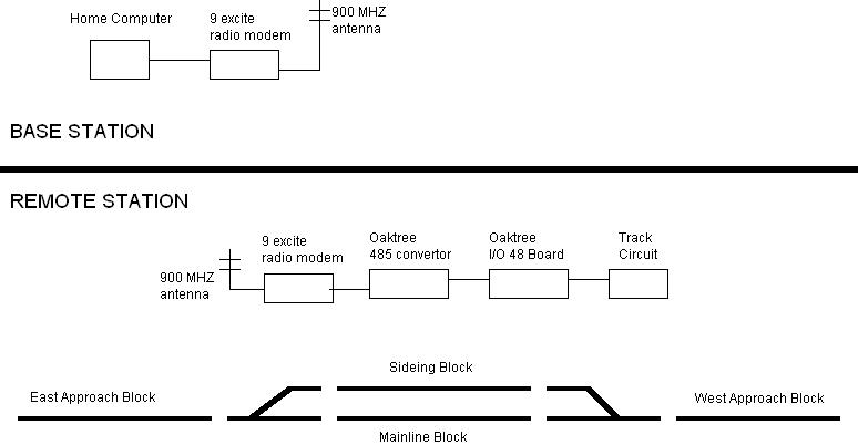
also use the Maxstream 9excite 900 MHZ radios to send a 232 signal
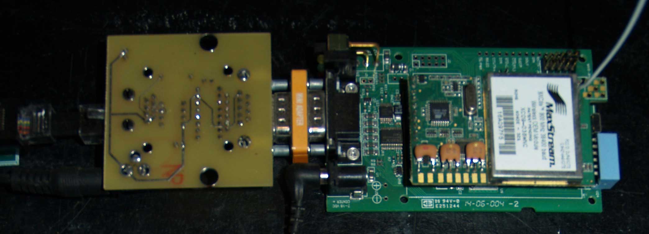
from This sounds complicated but it is really not. If you can plug a phone into an wall outlet you can wire the interface to your computer. The 232 signal needs to be converted because this type of signal from your computer will only travel a few feet before it gets degraded. The 485 signal is good for several miles with repeaters. You can just convert to a 485 signal at the computer and run telephone data line around your railroad to each IO-48 card. The cost of wire is close to the cost of just getting a low cost radio modem. The radio will also isolate your computer from the harmful electric currents that could exist outside like LIGHTNING. Pictured below is the radio modem (On the Right, Green board) and the oaktree 232 to 485 converter (On the left upside down, yellow board). The silver adapter between them is a 232 gender changer. Both boards have a female plug.
I
was buying the 900MHz 4mw Radio Modem Development Kit 38400 Baud from Be sure to pick a radio set that works for your conditions i/e distance from the Base Station to Remote Stations. The antenna has a lot to do with the distance the radio will work also. I use a 900mhz Wilson RV/Trucker Cellular Antenna on the base station this boosts the signal 10 to 15 dBi. The remotes have a 5 dBi magnetic mount 900 mhz cell antenna from HyperLink Technologies. I build a building near each sideing to house the electronics and power supply in. The power supply is a 12 volt lawn/garden battery that is connected to a 5 watt solar panel item 41144-4VGA from Harbor Freight The I0-48 board and the radio run on 12 volts. The 232 to 485 converter will need a 5 volt adapter like the Jensen Universal DC Adapter from Walmart set to 4.5 Volts. The newer Oaktree converters will run on 12 volts and do not need the 5 volt adapter. You should use a ground rod at each sideing. I have big lightning storms in my area so when not in use I disconnect the track circuit board from the IO-48 board. The track seams to act like a big antenna and attract the lightning. By using the ground rod the lightning will hopefully go to the rod instead of into the building. A set of knife switches could be used and opened between the track circuit and the railroad also. I have found that the micro chips on the IO-48 board do not really like lightning.
|
|
|
|
||||
|
|